
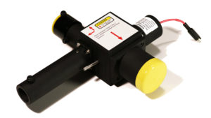
The SPPDI Model 1.3 is a compact general purpose laser optical interferometer. SPPDI is an acronym for Split-path Point Diffraction Interferometer. The SPPDI is a patented extension of the Smartt-style PDI (Point Diffraction Interferometer). (Reference R. N. Smartt and J. Strong, JOSA, 62, 737, 1972.)
In a Smartt-style PDI, interference fringe spacing and fringe visibility (contrast) are coupled, which reduces operational practicality. The SPPDI introduces additional optical components in the internal beam path to separate this coupling, greatly improving the available range for fringe spacing and fringe visibility (i.e., fringe contrast or dynamic range).

The SPPDI emits a diverging diffraction-limited probe or test beam that is precisely co-axial with the optical axis of the test article. This makes it possible to obtain direct on-axis measurements of optical components or systems ranging from very small to very large. Test beams with focal ratios as “fast” as f/4 (for example, f/2 concave mirror measured at center of curvature) may be measured. Test beams with even faster focal ratios, or optical systems with very short back focal distances, may be made with the addition of suitable beam forming optics in the external light path. Instrument-related error contributions may be measured and subtracted with the use of calibration optics available from Kerry Optical Systems.
The SPPDI reference beam is generated internally within the SPPDI by splitting off a portion of the test beam returned by the test article. This portion of the test beam is spatially filtered by a small pinhole aperture, thus generating a spherical reference wavefront, which remains co-axial with the test beam.
Interference fringes are produced by means of a pair of polarizing tilt plates, either or both of which may be adjusted by the user to cause a virtual displacement between the test and reference beams, as shown in the figure below.
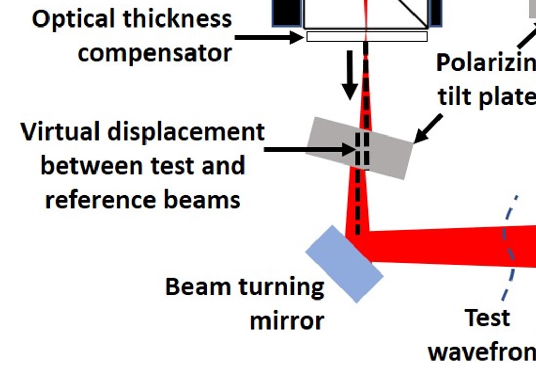
As can be seen in the figure, a virtual separation between the test beam and the reference beam is produced by tilting one or both of the tiltable, rotatable polarizers located inside the SPPDI enclosure. This enables an apparent separation between the diverging test and reference beams, thus generating interference fringes whose spacing and contrast are easily adjusted by the user. The tilt of the internal polarizers does introduce a small amount (typically <0.01 wave at 650 nm) of astigmatism, which is proportional to the tilt and the number of interference fringes. A simple equation is available (see the following section) to facilitate computation of the astigmatism, which is usually an insignificant contributor to the test beam wavefront error.
The compact size and sturdiness of the SPPDI enclosure helps ensure that the critical alignment of the internal signal and reference beam paths are maintained when exposed to the ambient environment. We are confident that the operational benefits and simplicity of operation of the SPPDI outweigh the added complexity, while retaining the core elegance and simplicity of the original PDI concept.
For a full description of the SPPDI, refer to the SPPDI patent document (United States Patent # US5457533, now expired), which can be found at the United States Patent Office website: www.uspto.gov.
![]()