
Known Sources of Aberration in the SPPDI
- The SPPDI produces a non-collimated output probe beam of laser light derived from an internal diode laser
- Low-cost bare diode laser chips emit radiation into a highly elliptical radiation pattern
- The apparent emission point of the radiation which leaves the laser chip depends on the angular position within the radiated elliptical beam, which leads to diode laser astigmatism
- The effect of the diode laser astigmatism is reduced to a negligible level by using only the central f/8 (or “slower”) central portion of the radiation leaving the laser chip
- The non-collimated laser probe beam will accumulate wavefront errors as it leaves and re-enters the SPPDI
- Spherical aberration is introduced as the probe beam traverses the internal SPPDI cube beam splitters and polarizer plates
- Astigmatism is introduced in proportion to the tilt of the internal SPPDI polarizing tilt plates
- Interference between expanding spherical wavefronts (signal and reference beams) produced internally within the SPPDI will produce hyperbolic interference fringes, but the departure from straightness over a centered f/8 beam is extremely small and can be neglected
SPPDI Theoretical and Experimental Tests
- Theoretical performance characteristics were predicted with the aid of ray trace software
- Experimental performance characteristics were evaluated with an f/8 beam produced by a 4.25” diameter concave spherical mirror (reference mirror) with a radius of curvature of 34″ (864 mm)
- Reference mirror was measured by Zygo Corporation
- Precision was evaluated by comparing results obtained with eight production SPPDI units against each other
- Accuracy was evaluated by comparing SPPDI results against the Zygo measurements, with the Zygo measurements considered as the “standard”
Theoretical Limiting Performance: Spherical Aberration
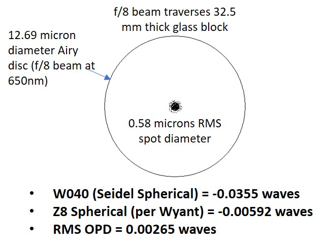
Compensating Wavefront Computation: Spherical aberration arises as the non-collimated signal/probe beam traverses 32.5 mm of optical glass inside the SPPDI. This small level of spherical aberration is intrinsic to the design of the SPPDI and is constant for a given focal ratio and wavelength. Because of this, it is possible to generate a compensating wavefront, which may be subtracted from the wavefront of the test article obtained with the SPPDI. The compensating wavefront is produced with the aid of a free software package known as DFTFringe, which is a general purpose interferometric fringe and wavefront analysis program produced by Mr. Dale Eason. DFTFringe may be downloaded from the internet and installed on a Windows®-based PC.
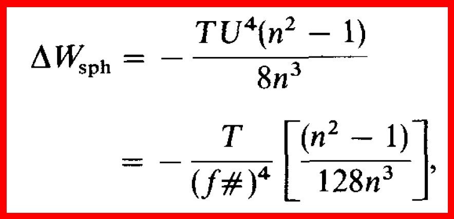
DFTFringe may be used to generate the required compensating wavefront by clicking “Simulations” -> “Wavefront” which will bring up the small “Wavefront terms” screen. All default setting can be left as-is, but the “Z8” radio button should be enabled by clicking it. The data field labeled Spherical (under the “Zernike Term” column) needs to be filled in with a value obtained with the aid of Equation 73 reproduced below, from Page 43 of the technical paper titled “Basic Wavefront Aberration Theory for Optical Metrology” by James C. Wyant and Katherine Creath. Equation 73 as given by Wyant and Creath, is:
Delta W-sph (the output of the equation) is also known as W040 or Seidel Spherical aberration. The value yielded by this formula is either divided by 6 (for analysis of a wavefront without regard to the surface which produced it) or divided by 12 (if evaluating the shape of the surface which produced the wavefront) to obtain the Zernike Z8 Spherical value. This value is entered in the “Spherical” data field in the Zernike Term column mentioned above. All other Zernike Term data fields should remain at 0.000. Generation of the correction wavefront for the SPPDI is then launched by clicking the “OK” button.
After the wavefront is computed, a graphical display of the correction wavefront will appear on the DFTFringe main screen. The Zernike Z8 Spherical value entered previously in the simulation screen will now appear on the left side of the DFTFringe main screen in the “Spherical” Zernike Term data field, under the column labeled “Wyant.” A value will also appear adjacent to it under the column labeled RMS. The RMS value will be equal to the Wyant value divided by the square root of 5.
T in Eq. 73 is the total thickness of the internal polarizer plates and beam splitter cubes through which the diverging/converging wavefront passes as it exits and then re-enters the SPPDI. T should be expressed in terms of the wavelength of light emitted by the SPPDI laser, which is typically 651.3 nm. f# is the focal ratio of the beam that exits and re-enters the SPPDI, and n is the refractive index of the internal polarizer plates and beam splitter cubes at the operating wavelength of the SPPDI. Alternatively, U in the upper version of the formula, is one half of the full angle in radians of the incident light cone which enters the SPPDI. The refractive index n is the refractive index of the Schott® BK7-equivalent glass comprising the SPPDI internal optical components. The value of n is 1.5145 for BK7 at a wavelength of 0.650 microns.
EXAMPLE: Given a thickness T equal to 50,000 waves (32,500 microns of optical glass / 0.65 microns per wave), an f/# of 8, and a value of n = 1.5145 at 0.65 microns, the amplitude of W040 obtained with Equation 73 above will be -0.03552 waves. This value is divided by 6 to obtained -0.00592 waves, which is then entered into the “Spherical” data field in the Simulations -> Wavefront screen. After clicking “OK,” the SPPDI spherical aberration compensation wavefront will be computed and displayed on the DFTFringe main screen.
The Spherical data field in the Zernike Term column on the left side of the main screen will be displayed with the value -0.006 (rounded from -0.00592), along with the value -0.003 in the RMS field (= -0.00592 divided by square root of 5 = -0.00265, rounded to -0.003). This SPPDI spherical aberration compensation wavefront may now be saved for future use by clicking the “Save Wavefront/s” option under the “Files” menu. This compensation wavefront may be subtracted from wavefronts obtained with the SPPDI for test articles which produce an f/8 beam. Other compensation wavefronts for other focal ratios may be computed and used in a similar manner.
NOTE: It is sometimes difficult to know if the wavefront computed by DFTFringe from an interferogram of a test article has the correct “sense,” i.e., whether or not the reported Zernike Z8 Spherical term should be positive or negative. The correct sense is easily determined by obtaining a second interferogram of the test article after slightly moving the SPPDI toward the test article. This should be reported by DFTFringe as a more negative value of the Z3 Zernike Defocus term. If the reported value of Z3 is positive, then the DFTFringe “invert” button should be clicked in order to invert the observed wavefront before subtracting the correction wavefront. Also note that the Z8 value produced by Eq. 73 will always be negative.
Theoretical Limiting Performance: Astigmatism
Compensating Wavefront Computation: Astigmatism arises within the SPPDI as the internal polarizing tilt plates are tilted away from being “normal” (perpendicular) to the internal signal and references beams. The larger the tilt, the higher the resulting fringe count (number of interference fringes) in the interferogram, and the higher the induced level of astigmatism.
If one of the two internal tilt plates is held “normal” (perpendicular) to the beam, the correlation between the number of fringes and the angular tilt of the tilt plates is given by the empirical formula Tilt = 0.3105 angular degrees per fringe. Thus, given the number of fringes in an interferogram, and the tilt predicted by the empirical relation, Equation 77 in the previously referenced Wyant and Creath document can be applied to predict the amplitude of the Delta-W-astig Seidel astigmatism.
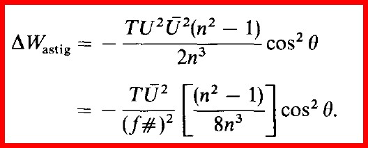
In Equation 77 U-bar is the angular tilt of the tilt plate in radians, T is the thickness of the tilt plate, f# is the focal ratio of the beam which enters the SPPDI, n is the refractive index of the tilt plates, and theta is the angular orientation of the tilt plate with respect to the local x and y axes. Cosine theta can be assumed to be 1 for the purpose of calculating the amplitude of the wavefront correction, which must then be apportioned in an RSS fashion between the local x and y axes. The actual amplitude of the Z4 (x-axis) and Z5 (y-axis) Zernike astigmatism terms is obtained by dividing Delta-W-astig by 2.
EXAMPLE: The tilt plates used in the SPPDI have a thickness of 3 mm and are comprised of glass which may be assumed to have a refractive index at 650 nm of 1.5145. For an f/8 beam and a tilt value of 3 degrees (0.0524 radians), the resulting Seidel astigmatism is 0.00595 microns, or 0.00915 waves at 650 nm. If the tilt plate is oriented so that astigmatism is only found in the x axis, the resulting Z4 Zernike term (after dividing the Seidel value by 2) is thus 0.0046 waves. The angular tilt of 3 degrees is obtained from the empirical relation Tilt = 0.3105 angular degrees per fringe. So, the interferogram relating to this example must have had 9.7 fringes.
Experimental Performance Tests — Evaluation of Precision (Unit-to-unit Repeatability)
Fifty-six full aperture interferograms of the reference mirror were obtained with eight different SPPDI units. When converted from the SPPDI measurement wavelength of 650 nm to the HeNe laser wavelength of 632.8 nm used in interferometric measurements provided by the Zygo Corporation, the results of these measurements are as follows:
- The average value of the RMS surface figure error was 0.0089 ±.0010 waves @ 632.8 nm, or 5.63 ±0.63 nm
- The average value of the PV (peak-to-valley) error was 0.0464 ±0.0059 waves @ 632.8 nm, or 29.4 ±3.7 nm
The standard deviation of these measurements indicate that the RMS and PV wavefront errors are consistent to better than 0.01 waves at 632.8 nm from one SPPDI unit to another. This is the basis for stating that the SPPDI measurements are precise (repeatable from one measurement to another and from one SPPDI unit to another) to within 0.01 waves.
Extreme care is taken to eliminate internal alignment errors as SPPDI units are constructed. Variations in precision of the alignment of the internal components will cause small differences on the order of a few thousandths of a wave in the values of the Zernike values. However, we believe that most of the variation in measurement results from one SPPDI unit to the next are due to variations in the quality (surface figure) of the beam splitters and polarizing tilt plates used within the SPPDI. Miniaturization of the SPPDI package and internal components guarantees that the footprint of the beam is kept small as it traverses the internal components, thus minimizing the accumulation of wavefront errors due to figure errors in the internal components.
Interferograms that form the basis of these statements about precision were recorded using a commercial 85 mm focal length f/1.8 mild telephoto lens connected to a digital camera with an APS-C size sensor. The amount of distortion added to the recorded interferograms by this lens and sensor system has been determined to be very small. This inference is based on measurements obtained with a variety of commercial camera lenses, and is affirmed by the Zygo results.
Experimental Performance Tests – Evaluation of Accuracy
Round Robin Test: A Round Robin test of a 6″ f/8 CerVit® concave spherical mirror was conducted by a large number of private individuals with access to interferometers of various types. The results of the Round Robin testing demonstrated that the SPPDI produces measurements that are very consistent with results obtained by other contributors.
Zygo Corp. Certification: Measurements of the reference mirror were made by the Zygo Corporation. Summary results at 632.8 nm are shown here.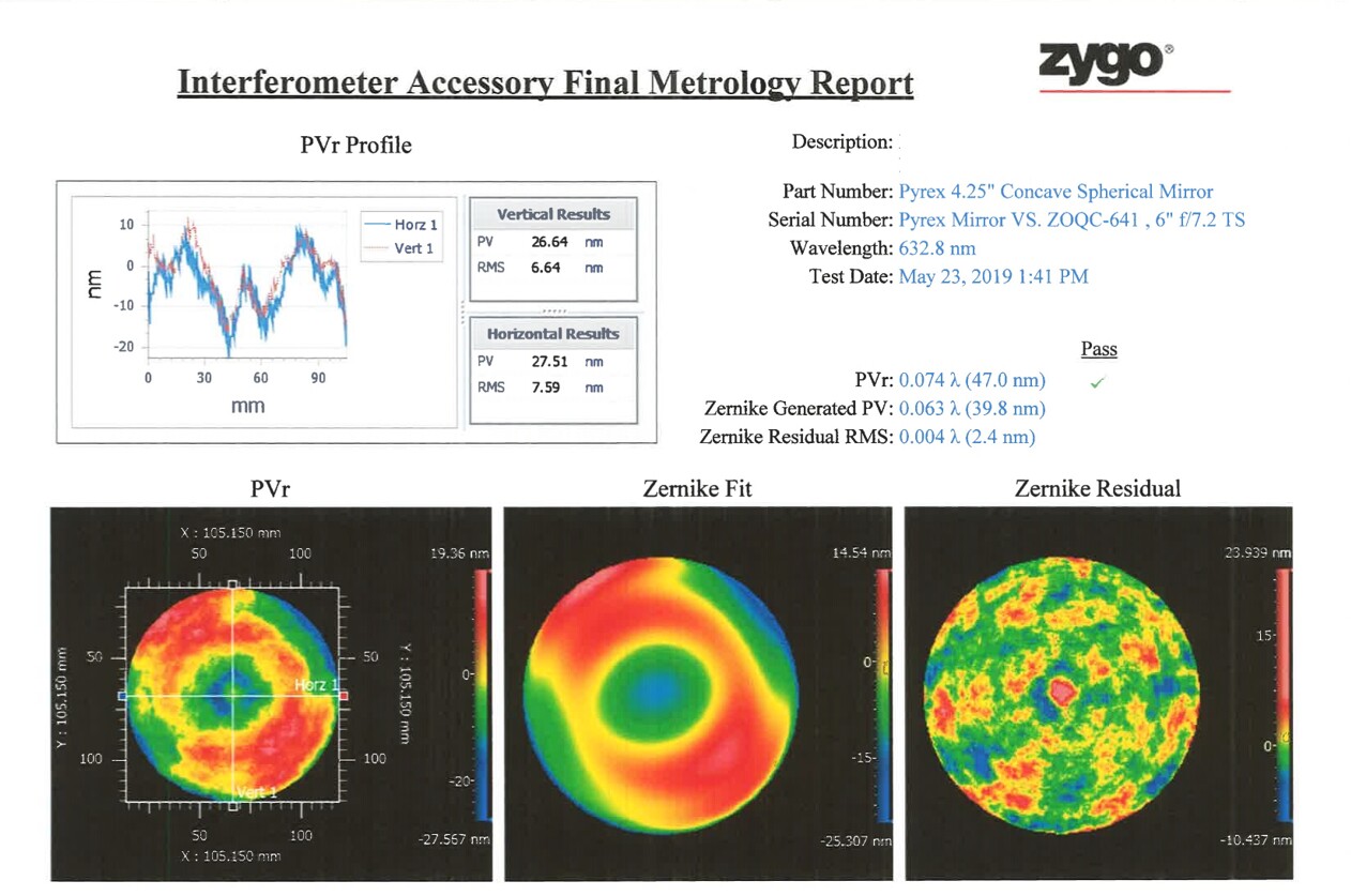
Summary of Zygo results vs. SPPDI results:
- Average PV error:
- Zygo: 27.08 nm
- SPPDI: 29.4 ±3.7 nm
- RMS surface figure error at 632.8 nm:
- Zygo: 0.0112 waves
- SPPDI: 0.0089 ±.0010 waves
- Zernike Term Z8 (Spherical) at 632.8
- Zygo: -0.0155 waves
- SPPDI: -0.01865 ±.0023 waves
Conclusion: These results provide confidence that the surface figure results predicted by the SPPDI units used in this study are both accurate and repeatable to better than 0.01 wave.
![]()